MEP Design
Mechanical, electrical and plumbing systems — designed, coordinated and issued as drawings, 3D models and specifications.

How we can help
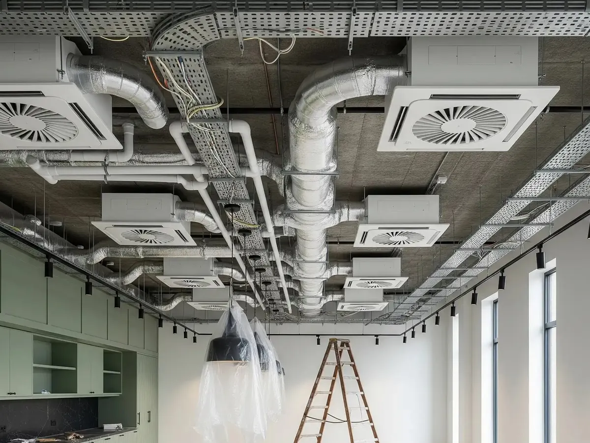
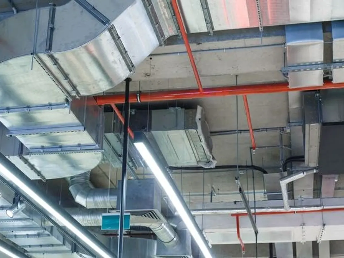
We design the mechanical, electrical and plumbing systems that make buildings work — for new builds, fit-outs and refurbishments across commercial, residential, industrial, healthcare, education and retail projects.
We coordinate building services with the information issued by the architect, structural and fire engineers and other stakeholders, identifying interfaces and reviewing design decisions before construction. M&E drawings are issued as a coordinated package with the calculations and schedules behind them.
Because we draw what we design, the same team produces the drawings, 3D models and specifications — clash-checked before they reach site — through to shop, fabrication and as-built drawings.
Systems we design
01Heating, ventilation & air conditioning
- Heating, cooling and ventilation strategies, plant and equipment sizing, ductwork and pipework routing, and heat recovery where it pays back.
- Heat loss and heat gain calculations and ventilation rates set against CIBSE Guides A and B and Approved Document F.
- Issued as system schematics, plant room layouts, ductwork and pipework drawings, and plant and equipment schedules.
- Plant space, riser routes and acoustic and anti-vibration provisions coordinated with the architect, structural and fire engineers and other stakeholders.
02Domestic hot & cold water services
- Cold water storage and boosting, hot water generation, pipework sizing and water hygiene provisions.
- Storage volumes, booster set duties and pipe sizes calculated from the fixture demand and the incoming supply pressure.
- Issued as distribution schematics, pipework layouts and plant schedules, with valve, insulation and trace heating requirements specified.
- Dead legs, turnover and temperature control addressed for Legionella control in line with ACOP L8 and HSG274 Part 2.
03Above & below-ground drainage
- Foul and surface water drainage, rainwater disposal and connections to the public sewer, coordinated with the structure.
- Stacks, branches and ventilating pipework sized to BS EN 12056, with external runs to BS EN 752 and Approved Document H.
- Issued as drainage layouts, manhole and invert level schedules, longitudinal sections and pipe sizing calculations.
- Invert levels, gradients and slab penetrations coordinated with the structural design, and connection points agreed with the sewerage undertaker.
04Electrical power distribution
- Incoming supplies, switchgear, sub-mains and final circuits, with maximum demand assessments and cable sizing.
- Cable sizes, protective device selection, discrimination, earth fault loop impedance and volt drop checked to BS 7671.
- Issued as distribution schematics, containment and small power layouts, distribution board schedules and load calculations.
- Intake position, metering and substation requirements coordinated with the distribution network operator and the building layout.
05Lighting & emergency lighting
- Lighting design to the required lux levels and energy targets, with emergency lighting to BS 5266.
- Illuminance, uniformity and glare assessed against the task requirements to BS EN 12464-1, with luminaire efficacy and controls set against Approved Document L.
- Issued as lighting layouts, calculation outputs, luminaire and control schedules, and emergency lighting drawings showing escape route coverage.
- Luminaire positions coordinated with the ceiling design and other services; emergency provision aligned with the fire strategy and escape routes.
06Fire detection & alarm systems
- Fire alarm categories and zoning to BS 5839, interfaces with other life-safety systems.
- System category, detector selection, zoning and audibility coverage set to BS 5839-1, or BS 5839-6 for dwellings.
- Issued as device layouts, zone charts, cause-and-effect schedules and a system specification.
- Interfaces with door release, lifts, smoke control and suppression agreed with the fire engineer and checked against the fire strategy.
07Fire suppression & sprinkler coordination
- Sprinkler and suppression provisions coordinated with the specialist designer and the wider services.
- Tank and pump room space, water supply and builder's work requirements established for the specialist's design.
- Head positions, pipe routes and ceiling interfaces reviewed against the specialist drawings to BS EN 12845 or BS 9251 as applicable.
- Issued as coordinated services drawings and a written review of the specialist package, with open items tracked to close-out.
08Data, communications & security
- Structured cabling, containment, access control, CCTV and intruder detection provisions.
- Comms room positions, containment routes and cable lengths set against the cabling standard adopted for the project, typically BS EN 50173.
- Issued as containment and outlet layouts, rack elevations, device and cable schedules and an outline specification.
- Power, cooling and access requirements for comms rooms coordinated with the electrical and ventilation design, and door devices with the ironmongery schedule.
09Building management & controls
- Control strategies, BMS points schedules and interfaces so the plant runs as designed.
- Set points, operating sequences, interlocks and alarms defined for each plant item.
- Issued as control schematics, points schedules, sensor and valve schedules and a controls specification.
- Interfaces with the fire alarm, specialist packages and the energy metering required under Approved Document L agreed and recorded.
10Renewables & low-carbon systems
- Heat pumps, photovoltaics and other low-carbon options assessed against the energy strategy and planning requirements.
- Options appraised on capacity, plant and roof space, electrical supply capacity and expected running cost.
- Issued as an options report with sizing calculations, plus layouts and schematics for the system taken forward.
- Assessed against Approved Document L and any local planning energy requirement, and coordinated with the structural and roof design.
11Lightning protection & earthing
- Risk assessment to BS EN 62305 and earthing and bonding arrangements.
- Air termination, down conductor and earth termination arrangements determined from the protection level established by the risk assessment.
- Issued as lightning protection layouts, earthing and bonding drawings, test point details and the risk assessment record.
- Main and supplementary bonding coordinated with the electrical installation to BS 7671 and with any structural steel or reinforcement used as a natural conductor.
12Load calculations, schedules & specifications
- Heat loss and gain, electrical loads, equipment schedules and NBS-style specifications that sit behind the drawings.
- Heat loss and heat gain to CIBSE Guide A, ventilation rates, water demand and electrical maximum demand calculated for each system.
- Issued as calculation outputs, plant and equipment schedules and clause-based specifications referenced from the drawings.
- Design criteria, assumptions and margins are stated so the figures can be checked and carried into the next stage.
13Drawings, 3D models & Revit documentation
- Coordinated drawing sets and federated models produced by the same team that designs the systems.
- Models built to the agreed level of information need, with naming, classification and parameters set at the outset.
- Issued as DWG and PDF drawing sets with RVT models and IFC exports where the project is running in BIM.
- Drawing registers, revision control and file exchange run to the project's information requirements and BS EN ISO 19650 where it applies.
14Clash detection & coordination
- Services coordinated against architectural and structural models, with clash reports issued before work reaches site.
- Federated model checked for hard clashes, maintenance access, insulation allowances and installation tolerances.
- Issued as clash reports with a numbered issue list, the federated model and marked-up sections through congested areas.
- Each clash is assigned an owner, reviewed at coordination meetings and closed out before drawings are released for construction.
15Shop, fabrication & as-built drawings
- Installation and fabrication drawings from the design, and as-built records at completion.
- Installation levels, support and bracket positions and module or spool breaks developed from the coordinated design.
- Issued as fabrication and installation drawings, spool and bracket schedules, and as-built drawings at completion.
- As-built drawings are updated from site records and contractor mark-ups for inclusion in the O&M manuals.
LET’S TALK ABOUT THE NEXT STEP
Talk to us about MEP design.
Share your brief, project stage and target dates. We’ll review what you need and clarify the scope before preparing a proposal.